|
We also offer a PDF version of this page: the manual that ships with your DMK AEM14. |
|
Congratulations on your purchase of a DMK Yacht Instruments AEM14 Analog Engine Monitor. The DMK AEM 14 is a NMEA 2000 analog engine monitor and a USB gateway in one device. The AEM14 works with analog sending units on your engine and outputs digital data sentences of live engine status. This data can be sent to a NMEA 2000 bus and, or directly to your personal computer via its USB Port. The DMK AEM14 is capable of monitoring 6 separate engine parameters and 2 battery bank voltages.If the AEM14 is connected to the NMEA 2000 bus, it will send engine data onto the bus to be viewed on other NMEA 2000 devices. If the AEM14 is attached to both a NMEA 2000 bus and to a PC through the USB Gateway, then any other NMEA 2000 data on the bus will be available to the PC along with engine data.
If the engine monitor is connected to a DMK 11A or 11A-GPS WiFi bridge, then engine data can also be received and monitored by mobile devices, such as iPhone and iPad.
DMK offers the AEM14 preconfigured with a wire harness and sender kit designed for Yanmar JH Series Engines. No calibration is required for this application.
There are two banks of switches inside the AEM14 that support the hardware configuration as shown in the following layout. Switch Bank A configures whether the AEM14 is working with existing gauges or not, and Switch Bank B configures the tachometer input to match the various types of sending units that exist on different engines.
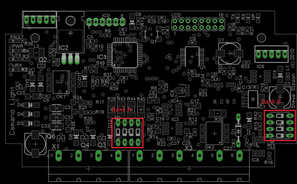
NOTE: The DMK Analog Engine Monitoring kit for Yanmar engines comes pre-configured with its own sending units for Coolant Temperature and Oil Pressure. It should not be necessary to change any of the internal switches if you purchased your DMK AEM14 as part of this kit.
The AEM14 has the ability to work directly with an engine sendor or jointly with existing gauges. If used jointly with a gauge, the Engine monitor picks up a signal from the gauge without affecting its operation. If the engine monitor is to be hooked directly to a sending unit without a gauge, the Engine monitor will need to supply its own current to the sending for proper operation. The Bank A switches set whether the DMK AEM14 will be connected to an existing gauge set or directly to the engine senders. If a gauge is present, this switch should be in the "OFF" position. If the Engine monitor will be the only device connected to the sending unit, this switch must be in the "ON" position to ensure the sending unit has the current it requires for operation.
Each of the AEM14 inputs can be configured independently using its own switch. See Figure 2 for the correlation of analog input to switch number in Bank A.
NOTE: The white portion of the drawing represents the switch. There are a variety of switch types, so the actual switch may not be exactly as shown. All switches are labeled with a direction for on or off and the switch number.
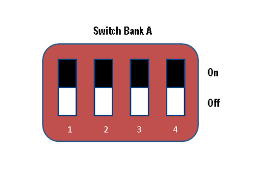
In Figure 2, position the switch to the ON position to supply current if no gauge exists and to the OFF position if the gauge exists.
| Switch number (from switch) | Function |
|---|---|
| 1 | Optional Analog Input 2 |
| 2 | Coolant Temperature |
| 3 | Optional Analog Input 1 |
| 4 | Oil Pressure |
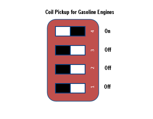
The DMK AEM14 has the capability to receive RPM signals from a variety of engine outputs. Switch Bank B is used to configure the AEM14 to different types of RPM Outputs. For diesel engines the AEM14 can either be connected to a low voltage magnetic pickup reading off of the fly wheel or it can take the signal from the engine's tachometer output. For gasoline engines, the signal can be taken from the engine's ignition coil or a tachometer output.
| Switch number (from switch) | Function (ON) |
|---|---|
| 4 | Gasoline Engine Type Sending Unit |
| 3 | Diesel Engine Type Sending Unit |
| 2 | Low Voltage type Diesel Sending Unit |
| 1 | High Voltage type Diesel Sending Unit |
Table 2 above. RPM sensor Configuration Switches: Switch ON the function that best fits the type of tachometer signal to be connected to the AEM14. For diesel engines switch both Diesel Type and select the type of sending unit to ON. If you are uncertain which type of diesel sending unit you have, try the high voltage selection first to see if it works. If not, try the low voltage selection.
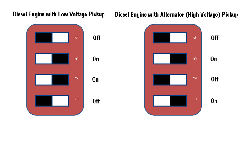
Figure 3 above. Diesel Engine Switch Settings: To select a Diesel Low voltage RPM sending unit, switch bank B would look like the example on the left, while a high voltage selection would look like the example on the right.
If a RPM reading is taken from a gasoline engine's ignition coil, have switch #4 "ON" and all other switches in the "OFF" position.
The AEM14 has four external connections.
- Power and battery connector. This is the small 4 conductor terminal strip connector. The device requires at least one of these power sources to be installed and powered to properly function.
- Sending Unit connector. This is the larger 6 conductor terminal strip connector. The engine's sending units attach to this connector.
- NMEA connector. This connector should be plugged into your powered NMEA 2000 bus.
- USB connector. If the device is to be used as a gateway a mating industrial USB cable should be plugged into this connector and plugged into your computer. If the device is mounted in the bilge and the USB interface is not being used, the USB connector should be sealed with an industrial cap.
Now that Switch Banks A and B have been configured, it is time to install and wire the AEM14 to the engine. It is not recommended to install the top of the box at this time since there are lights inside that will help with hookup and troubleshooting. The AEM14 may be installed in the engine space next to the engine, or it may be installed under the dash near any analog gauges. Choosing the best location will depend on if the AEM14 will be connected to standard gauges or directly to the sending units on the engine. Select a place that is reasonably well protected from vibration and can be accessed for troubleshooting. The wiring diagram for the terminal strip is shown in Figure 5.
The wiring diagram for the harness is shown in Figure 5.
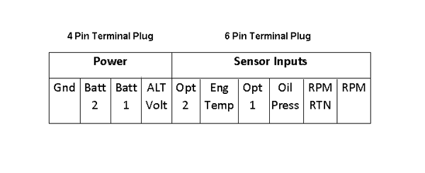
Ensure that the ground is a reasonable gauge wire (16 gauge or heavier) and is run to a good ground point. Usually there is a single ground point or ground bar on the boat that avoids ground loops and noise problems. It is important to get good accurate reading on the gauges be sure to respect good electrical installation practices.
You may monitor battery and alternator voltages separately. This is important if you use a battery isolator. If you do, the alternator voltage will be zero when the engine is not running and the batteries will show the correct voltage. If you do not use a battery isolator, the alternator voltage will read the same as the battery voltage. Ensure that you use a fuse on each of the battery/alternator lines separately. A 1 amp fuse is recommended for each power connection.
A note on Power: The unit uses power from any of Battery 1, Battery 2 or ALT voltage to power the electronics in the box. These connections should be hooked directly to the battery banks, unswitched through a 1 amp fuse. The device is internally switched on and off via the presence of power on the NMEA 2000 bus or the USB bus. When one or both of these signals are present, the device will draw from the battery connections for power. In the absence of power from the USB or NMEA connections, the device will shut off power from the batteries to preserve the batteries from discharge. You should switch the device on and off via the NMEA bus or by turning on your computer that is connected to the device via the USB bus.
Figure 6 is an example of how a normal installation of the engine monitor hooked into the gauges is accomplished. This diagram applies to all analog gauges including; oil pressure, engine coolant temperature, oil temperature, engine trim, transmission oil pressure, and transmission oil temperature. Gauges are labeled differently and some have nuts and studs, others have quick-disconnect spade type connectors. If you are unclear which wire is which, have a competent electrical installer do the installation for you. Once the engine monitor is hooked to each gauge then separately install the power connections directly battery connections.
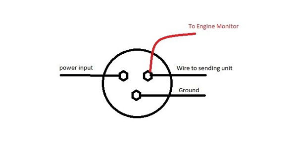
IMPORTANT NOTE
The power input for the gauges MUST be hooked to one of the power inputs to the engine monitor. You must note the input (Alternator, Batt1, Batt2) at the time that the device is installed as it will be used for calibration later during the install. Generally the gauges are powered by the alternator voltage or the engine battery connector. If this connection is not set properly during calibration the gauges will not read accurately.
You may choose which battery is house and which is engine and label them properly in the Coastal Explorer program.
Gas Engines. The tachometer connectors pose a special challenge. The tachometer has two connections (tachometer and tachometer return) that must be connected for proper function. On a gas engine the tachometer is derived from the primary of the spark coil and delivers a 200-300 volt spike. Care must be taken to wire the tachometer signal to the tachometer connection and the tachometer return to a ground point that is appropriate and away from the engine sensor. A separate wire to carry the ground signal to the engine block or the common ground point is best.
Diesel Engines. On a diesel engine, there are several different types of sensors. Some are from the alternator and some are from sensors on the flywheel. In each case, the safest ground point is off the engine sensor and back to the common boat ground. We will get to calibrating RPM later in Part II of this manual. Ensure that the switches discussed in the hardware configuration section are properly set.
If you will use the USB connection for calibration and configuration, plug in any type A to type B USB cable to the computer during the setup processes. Upon completion of the configuration, cap the industrial connection with the weatherproof cap. If you will be using the engine sensor as a gateway and an Engine Monitor, install the industrial USB connector and plug it into you navigation computer.
Install the NMEA cable in the NMEA connector and connect into the backbone with a Tee connector. The NMEA connection must provide NMEA power to the Engine sensor and must have another NMEA device connected to it to function properly. Ensure that the NMEA bus is properly terminated at both ends of the backbone to ensure data integrity.
Drivers must be installed along with Coastal Explorer to customize the calibration of the AEM14. Email sales@dmkyacht.com to receive the Configuration drivers and directions for installation. If you have purchased your AEM14 preconfigured then calibration is not required for it to function.
Calibration of the Tach and the analog inputs are required for the device to report proper values. If the device is installed correctly and gauges are displayed in the Rose Point product, it means the device is transmitting. Now is the time to perform a calibration. The gauges will be reporting incorrect prior to calibration. This does not indicate an error.
Once the drivers are installed in Coastal Explorer, pull down the options tab in the upper left corner of the display and select configure vessel and electronics. From this menu select engine monitor from the category pane.
You will see the following display:
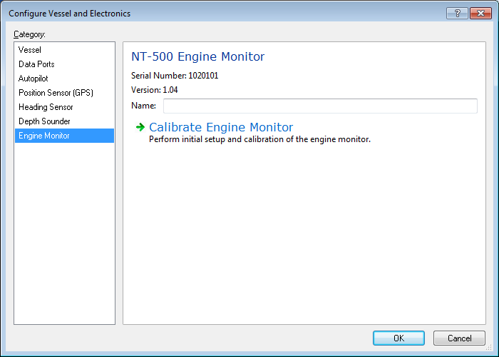
Note the engine monitor is detected and the serial number and firmware version are displayed. You may assign a friendly name, like "port engine" if you wish.
Click the calibration link and you will see the initial calibration page that looks as follows:

Recent Voltage
Prior to calibration the reference voltage must be properly selected. If you fail to perform this step the calibration will be inaccurate when your engine is started. The Engine Monitor must accurately know the voltage to the gauge so the appropriate adjustments can be made to the readings as this voltage varies. On the Engine Monitor setup select the proper reference voltage. This is the voltage input that matches the voltage connection on the gauges.
Selecting Other Gauge Inputs
At this point you may select the inputs you are using. (oil pressure, coolant temp etc) You should also set the type of engine (gas or diesel). The instance (generally port engine or single engine is 0 and starboard engine is 1)
Type: Select a gas engine or a diesel engine.
Hours: You may leave this setting at zero or set it to match your existing hour meter. This meter records hours based on actual engine running time, not by the time that the switch is on. This may cause some small variance from your hour meter after some time.
Battery Info: This device can monitor the voltage of two separate battery banks. The banks must be labeled separately for each bank of battery. If you have two engine monitors the battery banks must be labeled 0 and 1 on the first engine monitor and 2 and 3 on the second engine monitor. Each voltage reported on the NMEA bus must have a unique instance so it may be identified by the receiver. Friendly names can be assigned in Coastal Explorer when you are setting up instrument panels.
Connections: Drop down each connection and select the proper sensor that you have connected. If a device is not using an input, leave the setting as not used so the device does not send erroneous data.
Once this setup is complete, you may click OK to exit or move onto the next tab for this screen:

There is no need to discuss the four input tabs individually. The calibration process for the sensors is the same for each. The process should be repeated for each sensor you are calibrating.
- Calibration can be done in conjunction with a gauge if one exists. This is the quickest and easiest way to perform calibration. This method cannot be used unless you have a gauge connected with the engine monitor and a calibration tool.
- Calibration can be accomplished by several points and extrapolation.
- Calibration can be accomplished by physical measurement and recording.
A calibration tool is available from DMK for gauge comparison calibration. This tool requires the sensor be detached (either from the gauge or from the sending unit) and the tool will send levels in place of the sending unit. To use this method, detach the sending unit from the gauge or from the sending unit and hook one with of the tool to the detached wire. Attach the other end of the tool to a solid ground connection.
Steps to Calibrate:
- Rotate the knob on the calibration tool until the gauge reads its lowest reading. (this may be zero for oil pressure or 70-80 degrees for temperature.
- Click the endpoints on the line of the graph until you have one horizontal line where the orange numbers indicating the value match the gauge minimum value.
- Rotate the calibration tool until the gauge reads the highest value. Drag the point on the graph closest to the current point indicated until the orange number matches that of the gauge.
- By rotating the knob between the max and the minimum reading, you can adjust each point up or down to match the reading on the gauge.
The result may look something like the following figure.

This method requires using the engine itself to set several points in the curve and then extrapolating the curve from the collected data points.
- Once installed, turn on the ignition and observe the "baseline" of the line with respect to the gauge. Create a flat line at this baseline. (it will likely be zero for oil pressure and 70 degrees for temperature). See the following diagram:
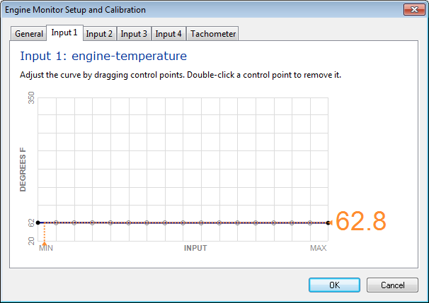 Figure 11.
- Start the engine and allow it to warm up watching the gauge carefully. As the gauge begins deflecting, move the points up or down to match the gauge. Until the engine has reached normal running temperature. The graph should then look like the following figure:
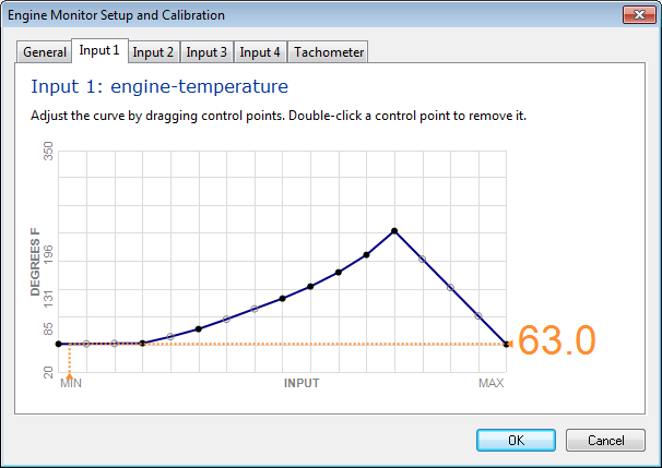 Figure 12.
- Start the engine and allow it to warm up watching the gauge carefully. As the gauge begins deflecting, move the points up or down to match the gauge. Until the engine has reached normal running temperature. The graph should then look like the following figure:
 Figure 13.
- At this point you can extrapolate the curve to the highest value on the curve and level out the tail to make your final curve.
This method is exactly the same as the prior method with the exception that you may not have a gauge available. In this case you must use a thermometer or pressure gauge to get the readings to set the values on the graph. This is a good technique to be used when older mechanical gauges are being replaced or if you have a way to measure the actual values that need to be set in the curves. A temperature sending unit may also be removed and placed in a pot of boiling water with a thermometer to create the curve as the temperature cools off.
All of these methods are more difficult to accomplish since they require an external means of measuring.
